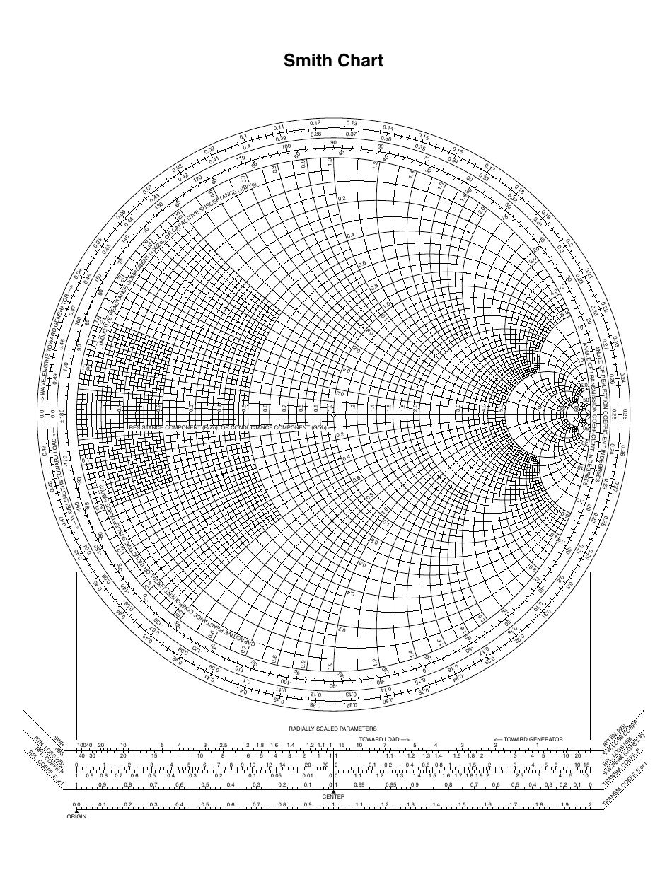
In a transmission line, when a wave of RF voltage and current encounters an impedance different from the characteristic impedance of the transmission line, Z 0, some of the energy in the wave is reflected back towards the wave’s source. R and X are the rectangular coordinates of the impedance. The vertical axis represents reactance (X): positive (inductive) above the origin and negative (capacitive) below. The horizontal axis represents resistance (R): positive to the right of the origin and negative to the left. Positive resistance which represents loss is on the positive X axis. Inductive reactance is positive (+Y axis) and capacitive reactance is negative (-Y axis). The X axis represents resistance (R) and the Y axis represents reactance (X). This graph shows the rectangular coordinates for any impedance. Graphically, these components are represented as a pair of axes at right angles, as in Figure 1.įIGURE 1. All impedances consist of resistance and reactance. The ARRL has made the QST articles available for downloading at Where Does the Smith Chart Come From?īefore discussing the chart, let’s back up a step. You can read these articles first or use them as references throughout this article. They provide as much background as you care to absorb, and deeper discussions than this article can provide.
#Y SMITH CHART UPDATE#
To update the Smith Chart tool with this change, click the Update button on the tool. You can change the active data plot in the Smith Chart from the Data menu or by selecting the data plot icon in the legend. If you have plotted multiple data sets into the Smith Chart, the Convert Data to Mag / Angle and the Reinterpret Data as Mag / Angle buttons act on the active data plot.

Click Normalize to perform the normalization.

Re-normalize the current Smith Chart by entering or selecting a factor, from the Factor combo box. Additionally, click the button to open the Smith Chart tool. To customize the Smith Chart, edit the Plot Details and Axes dialog boxes. In the opened dialog, click Reinterpret Data as Mag / Angle buttonĬlick the Smith Chart button on the 2D Graphs toolbar.Highlight the X and Y columns and plot a Smith Chart.If what you have is Mag and Angle(in degree) data for and want to plot a Smith chart from them, Requires a selection of at least one Y column of values and an associated X column īy default, the X and Y columns are treated as real part and imaginary part of Zl.


 0 kommentar(er)
